Combined optical-electrical-thermal simulations in CST
Published:
In this post, I describe how to set up a multi-physics co-simulation model in CST Microwave Studio.
The co-simulation model is usually used when we need to study different physical effects of the device. Here, I’ll present a step-by-step procedure to set up a model consisting of electrical-thermal-optical models.
First, create your model and specify all parameters and boundary conditions. Then, follow the steps described here to set up co-simulation model.
Electrical Simulation
Select the schematic view of the project.

Select Tasks and from the drop-down menu, click on New Task.

Select Simulation project and click OK.

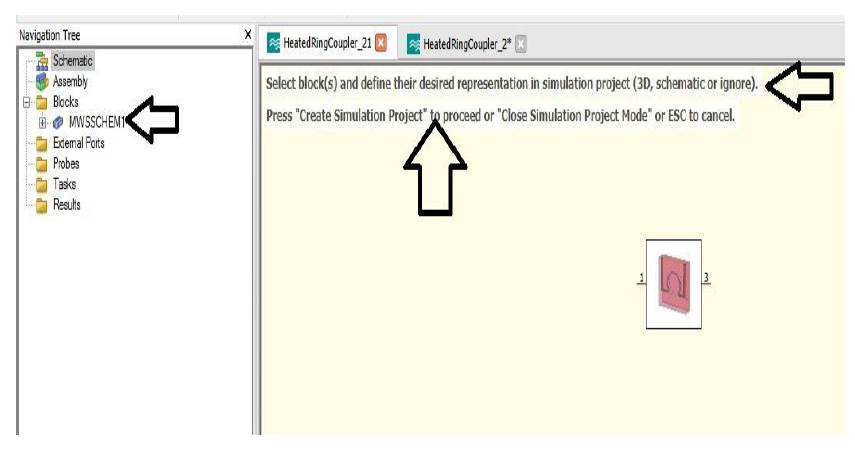
Then select MWSSCHEM.
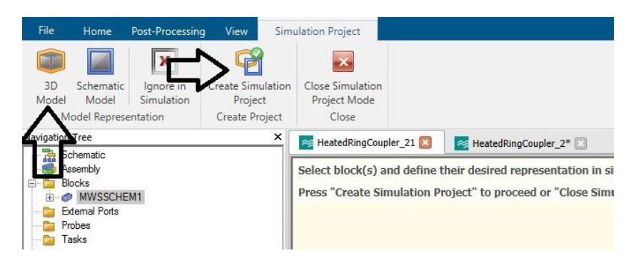
Click on 3D Model, and after that, click on create simulation project.
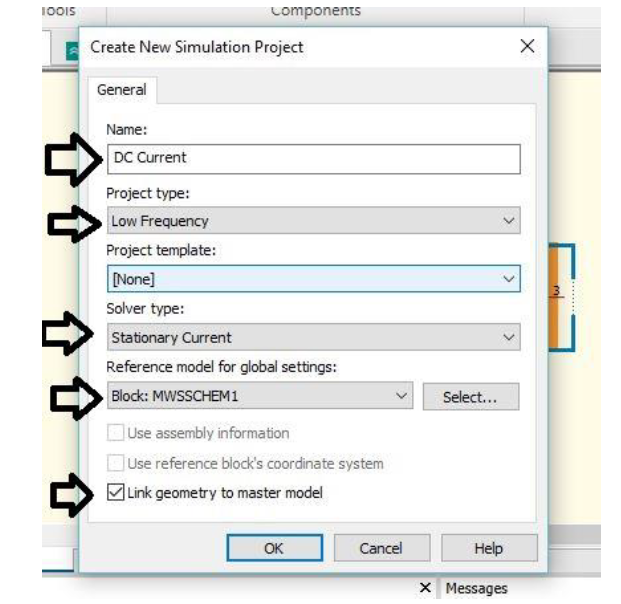
A window as shown below will open. Select the following options from the drop-down menu. This will create an electrical simulation project.
In this project, specify all the relevant material parameters and boundary conditions. To apply the voltage on the electrodes, the electrodes should be defined as the perfect electric conductor (PEC) otherwise, the voltage can not be specified on the material.
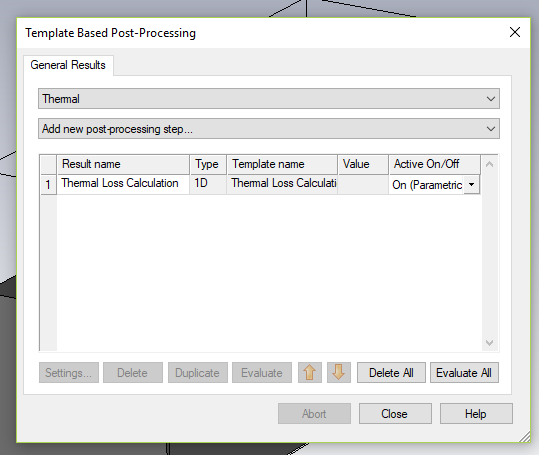
After defining all the parameters, the thermal loss term is exported via Thermal Loss Calculation from the post-processing window.
The electrical simulation is complete now you can run the simulation and see the voltage and current distribution in the device. To see the temperature rise due to the current flow, we set up a thermal simulation.
Thermal Simulation
Electrical simulation task is complete, and now we create the thermal simulation. For this, we go back to step one, i.e., schematic view of the original project.
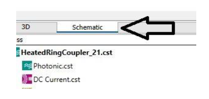
Then select the New Task.

Now, repeat the step 3, 4, and 5.
Select the following options as mentioned below for the steady-state thermal simulations. For the transient thermal simulations, select Thermal Transient instead of Thermal Steady State.
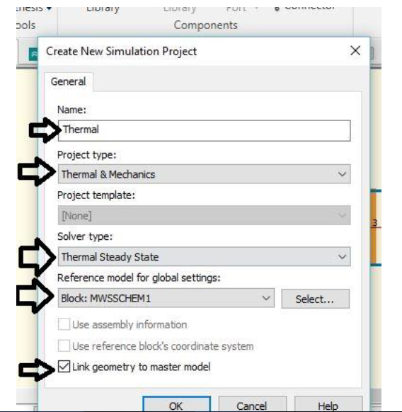
Now, define the boundary conditions, thermal properties of materials, temperature-dependent refractive index and follow the next step to import loss term from the electrical model.
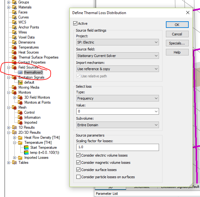
In the case of a steady-state solution, a time signal is defined in the excitation signal option by double-clicking the default folder and selecting the fill the time according to our choice.
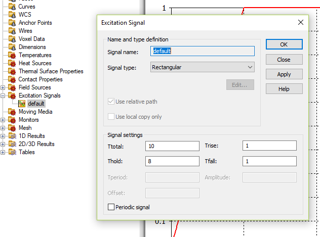 Run the simulation and see the temperature distribution in the device. To calculate the effect on the optical behavior of the device due to a temperature change, we set up an optical simulation.
Optical Simulation
- Now, we create the photonic simulation project for this again, we go back to step one, i.e., schematic view of our original project. The next four steps are similar to the electrical and thermal simulation project.
Select as described below.
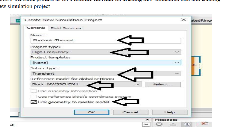
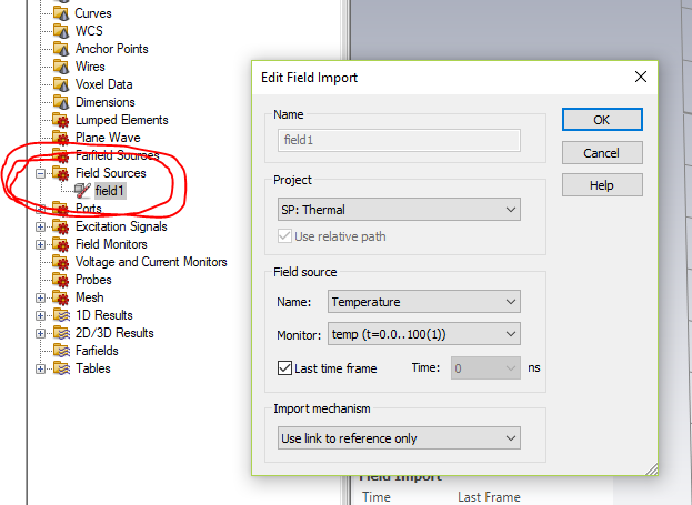
After this, we import the thermal losses from the thermal model into the optical simulation by selecting the field source.
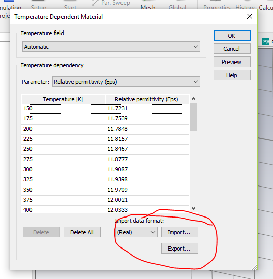
- To extract temperature-dependent optical properties, we add temperature-dependent epsilon values into the CST by import option.
Finally, make sure that all the material parameters are properly defined. Run the complete co-simulation by clicking update from the schematic view of the original project. It will automatically run all the simulations.
